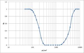
PMMA resists work positively under standard conditions. The long polymer chains are broken into small fragments by the irradiation process. PMMA 950k with a molar mass of 950 000 g/mol is primarily reduced to a molar mass of about 5000 g/mol. These short-chain polymers are readily soluble in the developer, which is not the case for the polymer with the initial high molar mass. If PMMA layers are however irradiated with an at least tenfold higher dose, so many radicals are produced that all PMMA polymers, large or small, are intensively crosslinked. Under these conditions not only longer chains are rebuilt, but also highly insoluble layers are formed due to the crosslinks. Fig. 1 shows the gradation curve of a standard PMMA. Up to more than 1000 μC/cm², the gradation curve corresponds to the curve of a “normal” positive process. Above 2000 μC/cm², the recombinant crosslinking process prevails, and at about 7000 μC/cm² the layer is completely crosslinked which makes the layer more insoluble than the unexposed initial layer. If negative PMMA structures should be used, a stronger developer than for the positive process is required. Here, the non-irradiated layer is to be removed while the crosslinked surface remains.

Fig. 1: Positive and negative gradation curve of a PMMA e-beam resist
This effect can even occur during SEM observations. If a PMMA structure is scanned with electrons of the SEM for a longer time, this section can later not be removed any more.
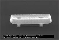
Striking examples for the use of the negative mode are the bridge structures produced by Prof. George Schmidt at the University of Würzburg. At first, the bridge body is written at a very high dose, but at an acceleration voltage of only 1.5 kV. As a result, electrons penetrate only about 200 nm deep into the PMMA layer, but crosslink this volume completely due to the high dose applied. Then the bridge pillars are written, again with a high dose for crosslinking, but this time with high acceleration voltage which crosslinks the pillar down to the bottom. The bridge structure is then released with a strong developer (see figures).

Fig. 2: Bridge structure with 2 pillars

Fig. 3: Bridge over topologies
Overview E-beam Positive
